
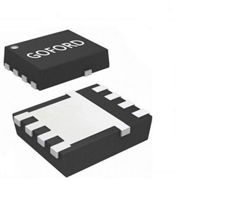






BESS MOSFET Selection Guide: Pre-Charge, Main Relay & PCS Circuits
2026-07-15
BESS systems operate under extreme conditions: high voltage, heavy current, wide temperature cycling, and 24/7 continuous operation. Power semiconductor devices face far stricter validation standards than standard industrial power supplies.
Within a complete BESS, MOSFETs serve three core functional circuits, each with distinct performance demands:
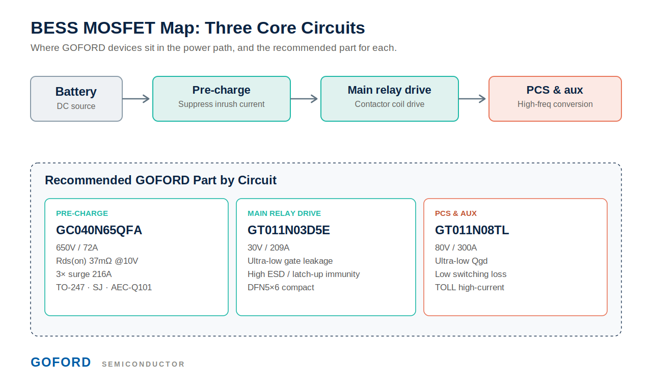
1. Pre-Charge Circuit - suppresses inrush current during power-up under millisecond-level pulse stress. Key metrics: wide SOA, high peak drain current (IDM), ultra-low Rds(on).
2. Main Relay Drive Circuit - drives the main relay / contactor coil under continuous live operation. Requires automotive-grade reliability, ultra-low gate leakage, and strong latch-up immunity.
3. PCS Auxiliary & Low-Voltage Side Circuit - high-frequency switching for maximum energy efficiency. Critical specs: low Qgd, minimized switching loss, superior thermal stability.
Generic off-the-shelf MOSFETs frequently suffer three common failure modes in BESS applications:
• Device burnout when the pre-charge pulse exceeds SOA limits.
• Severe Rds(on) drift and rising leakage after long-term thermal-cycling aging.
• Degraded reliability and shortened service life caused by constant vibration and continuous current loading.
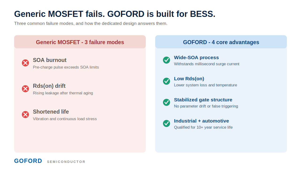
GOFORD delivers an all-in-one MOSFET solution fully optimized for the complete BESS working envelope, with core advantages as below:
✅ Wide-SOA process to withstand millisecond-scale surge current impact.
✅ Low Rds(on) design cutting system power loss and operating temperature.
✅ Stabilized gate structure eliminating parameter drift and false triggering during long operation.
✅ Industrial and automotive dual qualification, supporting 10+ years of BESS service life.
GOFORD Recommended MOSFET Series for BESS
1. Pre-Charge Dedicated MOSFETs
Application: High-voltage pre-charge loops in BESS string architecture.
Highlights: Extra-wide SOA, high surge-current tolerance, low conduction loss.
GC040N65QFA (preferred, high power)
(1) Super-junction (SJ) process with wide SOA to withstand pre-charge inrush; 3x rated surge current up to 216A.
(2) Low Rds(on) of 37mΩ @10V for low conduction loss and heat, ideal for 24/7 energy storage operation.
(3) AEC-Q101 automotive-grade qualified for long-term BESS reliability.
(4) Electrical specs: 650V / 72A, Pd 496W, Qg 158nC, package TO-247.
GC085N65QFA (high-density, automotive)
(1) Super-junction process, wide SOA, 3x rated surge up to 120A.
(2) Rds(on) 72mΩ @10V, Qg 76nC, compact TO-247 for high-density layouts.
(3) AEC-Q101 qualified; electrical specs: 650V / 40A, Pd 299W.
Note: depending on the actual DC platform, alternative GC-series voltages (up to 800V) can also be selected.
2. Main Relay Drive MOSFETs
Application: BMS main-relay / contactor coil drivers.
Highlights: High long-term reliability, ultra-low leakage, strong anti-aging performance.
G2305
(1) Ultra-low gate leakage, minimal parameter drift after long-term thermal cycling.
(2) High latch-up immunity and ESD protection for contactor inductive spikes.
(3) Compact SOT-23 package, ideal for BMS main-relay drive circuits.
(4) Specs: 30V / 5A, operating temperature -55°C to 150°C.
GT011N03D5E
(1) Ultra-stable gate structure for long-term 24/7 energy storage operation.
(2) Enhanced ESD and avalanche resistance, high reliability under continuous live load.
(3) Low leakage minimizes static power consumption of the BMS system.
(4) Specs: 30V / 209A, DFN5×6 compact high-current package.
3. PCS & High-Frequency Loop MOSFETs
Application: Power-conversion stages and auxiliary power supplies.
Highlights: Low Qgd, superior energy efficiency, optimized for high-frequency switching.
GT011N08TL (top choice for high-power PCS)
(1) Optimized ultra-low Qgd to cut high-frequency switching loss.
(2) Balanced conduction and switching loss for superior full-load efficiency.
(3) Low parasitic capacitance, EMI-friendly for high-frequency PFC and bidirectional DC-DC.
(4) Specs: 80V / 300A, TOLL high-current package.
G20N03D2 / G3404LL (mini high-frequency auxiliary power)
(1) Minimal Qg for ultra-fast switching at light load.
(2) Tiny package saves PCB space for control-board auxiliary circuits.
(3) Low power consumption to improve standby efficiency.
(4) Specs: 30V, compact DFN2×2 / SOT-23-6 packages.
Competition in the BESS industry now centers on both safety and energy efficiency. Proper MOSFET selection drastically reduces system failure rates, boosts overall efficiency, and extends the full lifecycle of energy storage equipment.
Open to all BMS, energy storage and PCS engineers for technical discussions covering BESS power device selection, pre-charge circuit optimization and reliability improvement.
 Latest news
-
2026-09-16
GOFORD Semiconductor at Electronica 2026
-
2026-09-01
High-Frequency Inverters 2026: 20kHz+, Miniaturization & SiC Synergy — How to …
-
2026-08-13
Data Center BBU Power: Key MOSFET Selection Criteria & Goford Solutions
-
2026-07-31
MOSFET: The Unsung Core of All Power Systems
-
2026-07-15
BESS MOSFET Selection Guide: Pre-Charge, Main Relay & PCS Circuits